Monday, October 23, 2017

Blender 3D VW Dune Buggy Project

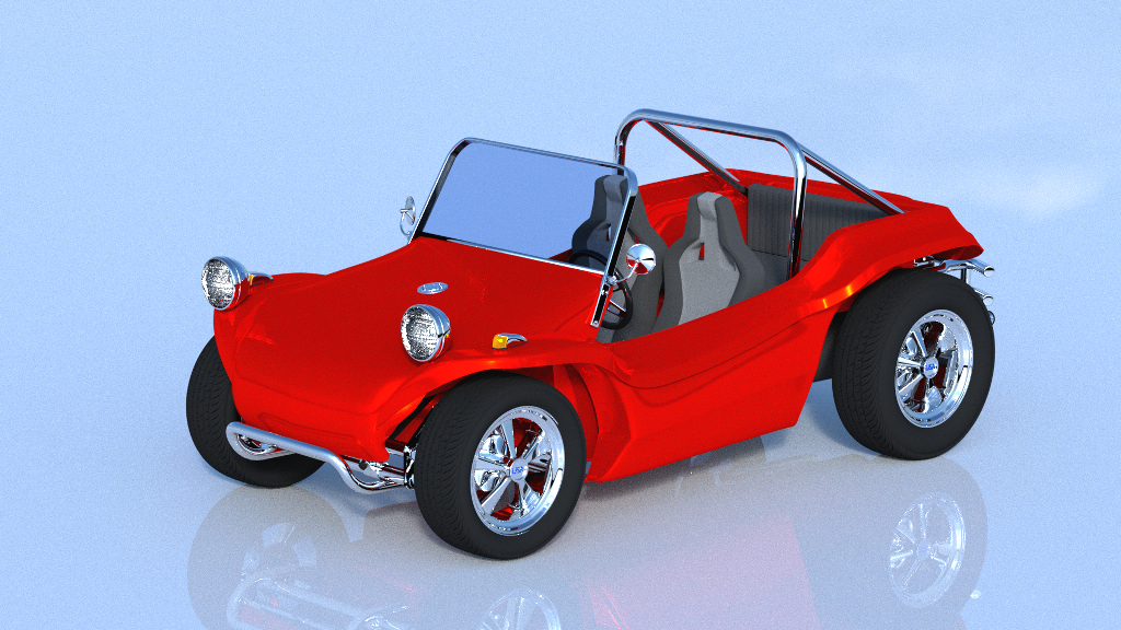
With summer gone and fall nearly over too I was inspired to model something in Blender 3D that has been on my wish list for a lot of years.  As most of you who follow my blog have seen I have modeled a number of vehicles over the years and so I just had to add another one of my favorites.  I did my homework and modeled this VW dune buggy.  This was an interesting project, as my research that I found about this type of vehicle is that none of them are exactly the same.  Similar yes but not exactly the same. All of them are custom built to at least some extent. So it gave me a lot of leeway to model the dune buggy the way I think it should be or will be if I ever pull the trigger and actually build a real one for myself. So this is how it all turned out. 

(Click on the photos for a larger view)

My Blender 3D model of the dune buggy turned out very well I think.  The big problem that I found in starting to model the car was finding the correct views that I needed to get everything scaled correctly to make the car look right. As usual there are things I am sure would stick out like a sore thumb if I owned a real dune buggy like this and knew more about it in greater detail.  It is modeled after the very first dune buggy called the Meyers Manx  that has been cloned by a lot of companies over and over again for real over the years.  But in my eyes this is the only real dune buggy design.  Only a few off brand dune buggy makers even come close to the original that was created by Bruce Meyers.


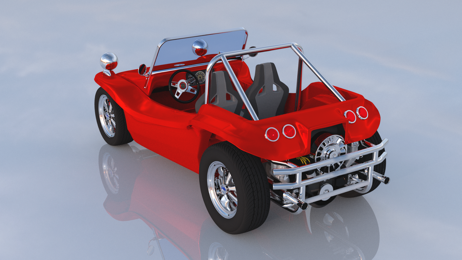
Another tricky part about modeling the car was getting an engine put into it that even looks something like what should be in a dune buggy.  Again it was hard to find photos of just the engine in a car that was not at least partially covered up.  So I pieced what you see together to hopefully look right.  So if you see something totally out of place here please forgive me for not getting it exactly right.  All I can say is I tried and hopefully you approve of my efforts. 


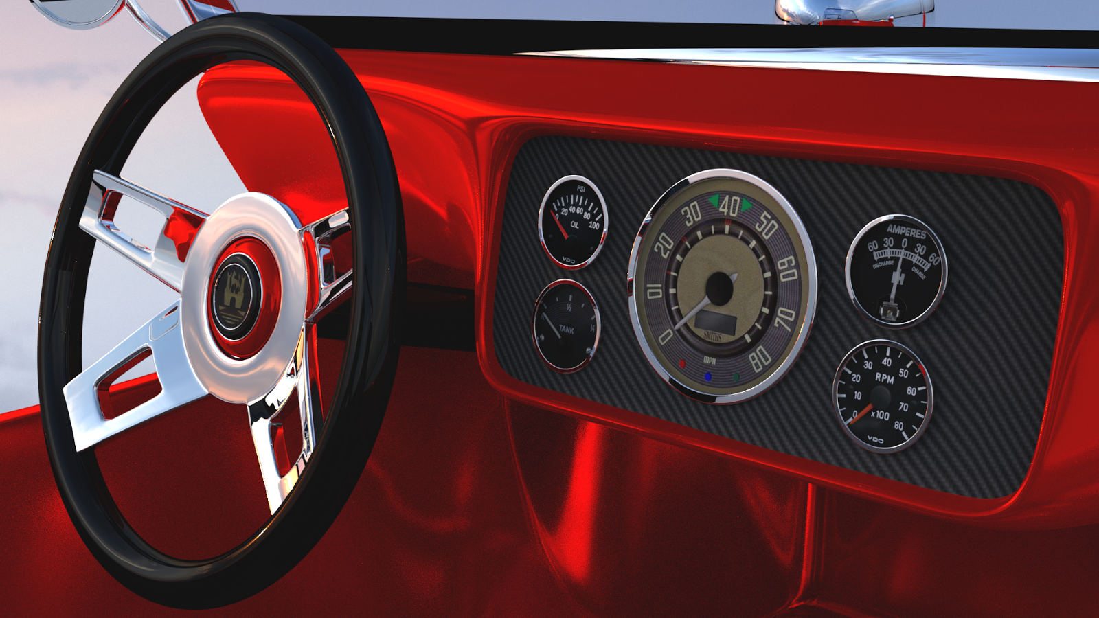
The dash was the only thing that I think could be actually accurate in a real dune buggy. The gauges in my model are correct as I was lucky enough to track down the exact VW gauges that would or still could be used in a dune buggy today.  So I am happy with the results on this end of the model. I especially like the carbon fiber dash and the steering wheel. 


Lastly what could be more fitting for a dune buggy than having it parked on a nice sunny beach.  Someday my real dune buggy will be parked on a beach too..... I hope.  Until then it's nice to be able to make another vehicle for my portfolio and dream.  Enjoy the images.


Monday, October 16, 2017

The Tin Man Project Is Completed!

I am happy to report that I have finished the Tin Man project in the workshop this afternoon. It has not been a terribly difficult project to design or build which is always good and the end result was worth the effort.  So let me show you how it all turned out. 

As you can see the Tin Man has a great big grin on his face to match the one that is on my face now that the project has been completed.  He stands 30" tall and has over 200 parts.  The body was made out of fiberglass, the arms and legs are PVC pipe, and everything else was 3D printed except for nuts, bolts and a little wood for the axe handle.  In his right hand he is holding his trusty oil can and of course he had to have an axe that is sitting next to him.  

Here all off the parts laid about before I started the final assembly of the Tin Man which took around 2 hours to complete.  The axe is around 12" inches long with a real wooden handle and the head of the axe being 3D printed in ABS plastic.  I am very happy how this turned out.  


Here's a closer look at the axe along with the little oil can for the Tin Man.  I was lucky enough to track down actual photos of the oil can so I could model it in Fusion 360 CAD software and then 3D print it in parts.  I then sanded everything smooth and glued it together and painted it silver. 


The only parts that are glued in place on the Tin man is his big toothy smile and his big red heart.  Lots of planning went into this project so I am happy once again that my efforts worked out the way they did.  This will be a great lawn ornament and I suspect he will look even better once he has been out in the weather for a few months.  It will make him look a lot older but if he every gets to be to worn looking it is an easy matter of taking him apart and repainting him if need be. 

I was happy that I was able to take the photos that you see here in the workshop today.  I was not sure he could stand up on his own. But for use in a yard I have a wooden dowel that would be pounded into the ground to support him by using a receiving tube that runs up the inside of his back that the dowel would slide into.  This will keep him standing even in a very strong wind.  I suspect though that even if the Tin Man fell over in a lawn the worst that would happen is that he might get dirty.  A very sturdy fellow to say the least.  Another project that I can cross off the list of ideas that keep coming up in my head.  Enjoy the photos and have a good day in your shop as well. 

Wednesday, October 11, 2017

How To Get Free CAD Software From Autodesk!

Next week I will start teaching a class on how to use Fusion 360 CAD software at the Key City Creative Center in Dubuque, Iowa.  With this being said I have been getting my new students ready for the class by first helping them get Fusion 360 software set up on their laptops for free.  I have been using this software for three years now and I am more than happy with it's capabilities, regular updates, and of course the fact that anyone can get a copy for free.  So after having sent out to my students the procedure to do just that I thought it would be a good idea to spread the word to everyone else that reads my blog as well.  So here are the steps you will need to take to get this great CAD software for your next project. 


Fusion 360 Setup

Go online and enter Autodesk.com/products/fusion-360/overview


When page loads up select "Download Free Trial"


Enter Your email address and select "Download Free Trial" again.


Fusion 360 will auto-launch once setup is complete.
A window will come up asking you "Do you want to run this file?"
Select "Run"


Setup will begin..... this will take a while to complete.


Another window will open up to sign in.
Select "Create Account"


Fill in information
Select "I agree to terms"
Select "Create account"


Select "Done" in account created window


Fusion will finish setting up


Press "Continue" on this screen


Fusion 360 will start showing "Welcome to Fusion 360" pop up window
Select "Next"


The data panel window will open
Select "Done"


Getting started window will open
Select "Close"


Select blue button "Term ends in 30 days" on top of screen
A new window will open
Select "Sign up as a Start-up or Enthusiast (Free)


Select "Accept Terms"
Select "Submit"


Select "Close" to end sign up screen


Fusion 360 is now ready to use.

That's all there is to it.  Follow the steps one by one and in a very
short time you will have access to this amazing free software.  I use
it always to design and build the projects that you can find here on
my blog.  It's a great tool and there are lots of training videos online
to help get you started.  Tech support from Autodesk with the
software also is excellent so it's a no brainer to get started designing
you next great project.  Happy creating!

Monday, October 2, 2017

The Tin Man Project Part 3

The Tin Man project is progressing nicely with primer and paint being applied to the parts this week.  Hopefully I will have the project completed by the end of the week.  Here are some images of where the project progressed over the past week or so and stands as of this morning.
\

This is the start of the construction of the body for the Tin Man.  I stacked up four layers of Styrofoam and glued them together to make a nine inch tall cylinder.  After sanding one edge of the cylinder I fiberglassed it completely except one end and let it cure over night.  Next I marked and cut what will be the lower edge of the fiberglass body to get a nice straight edge using my bandsaw.  


Here you can see the Styrofoam sticking out of the body before I started to remove all of it,  This way I could have the cavity I need to mount the arms, legs, and head.


This strange looking device is what is called a hotwire.  It is the tool that I used to remove the Styrofoam from the body of the Tin Man.  Electrical current is fed into the device which heats up the wire to melt the Styrofoam.  A great tool that I have used for years and is well worth the money.


Here I started taking out pieces of the Styrofoam with the hotwire. The tool made it as easy as scooping ice cream out of a bucket.  I wrapped the Styrofoam in plastic sheeting before I started fiberglassing.  This made it simpler to remove the Styrofoam as the fiberglass did not stick to the plastic sheeting.  This left me with a lot less clean up inside the Tin Man body and a nice smooth surface as well.


 Here the body has been completely cleaned out.  If I had not wrapped the foam first in plastic sheeting I would have had a lot more clean-up to do on the inside of the body.  It saved me a lot of work to be sure. 


Here is a look at the 3D printed mounting plate for the hip and legs that is now installed into the body along with a mounting tube to receive the rod that will be pounded into the ground to help support the Tin Man when he is standing on display.  The rod slides into the tube and will hold the Tin Man up even in a stiff wind. 


I next started putting the arms together for the project.  On the left you can see the first set of bolts and nuts that I used to put the assembly together.  I was not happy with the look so I swapped everything out and used threaded rod and acorn nuts on most of the assembly.  This took me a bit longer to make and assemble but the look is much cleaner.  


Finally on to the priming and painting of the parts for the Tin Man.  Here is a shot of most of the parts on the work table.  The joints for the legs in the project needed very little prep work so I was able to go ahead and prime and paint these parts first. 


Lots and lots of parts had to be 3D printed to make the joints for the arms and legs. 


Then you have lots and lots of nuts, bolts, and threaded rods to hold everything together. In total there are 206 parts in the entire project. 


The Tin Man's face is coming right along with the first couple of coats of primer.  I still have a little wet sanding to do yet on this part but it should not take me very long to get it dialed in.  The head of course will be painted silver like the rest of the figure.
 

The body of the Tin Man still will need a bit of work yet before I am happy with the outer surface so that I can spray on the paint that it needs. I'll get there but it will take a little more time. 


Here the arms, legs, and hands along with the head of the axe for the Tin Man are painted and left to dry. This was the easiest part of the project as these parts needed little if any prep work to get them ready for paint. 


Lastly what self respecting Tin Man would be without his trusty oil can.  This turned out very well and took a bit of thinking to get it printed correctly but will be a nice accessory for the project.  I still have to do some sanding on the individual parts of the oil can and then glue them together and paint it.  I was lucky enough to find an image of the actual oil can used in The Wizard of OZ so I am happy to include this with the Tin Man when he is on display. 

Part four of the project should wrap things up with this project so check back to the site soon to see how it all turned out.