After waiting four years to make it all happen, this past week to the day I received my new Honda Goldwing motorcycle that I lost back in 2012. If you had not been reading my blog back then I had a major fire at my house on October 4th 2012. With the fire I ended up losing my Honda Goldwing, my Mini Cooper, a custom cargo trailer for the bike, a custom built 15' kayak, tools, camping gear and damage to my house on top of it all. So I am very tickled to finally get back what I had lost four years ago.
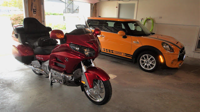
Here is my latest addition to my garage. A pretty terrific pair of vehicles to say the least. But to the point of this post is the GPS that I have been working on installing into the Goldwing. My original Goldwing that I lost in the fire had a GPS built into it. It would have cost me an additional $3000 to have this same bike so I opted to saving a bunch of cash and mount an aftermarket GPS from Garmin instead. After doing some research on what exact model GPS I wanted for the bike I then had to figure out how to get it powered and mounted properly.
I had found some pretty ugly installations online by other riders that were nothing like what I wanted for the mounting or the power. Even my dealer suggested that I cut a notch into the front fairing so that the power wire could be routed underneath an access compartment door to the outside GPS. No way was I going to start carving up a brand new Goldwing in this manner. There had to be a better way. So let me show you what I came up with.
Here is the GPS I choose for the Goldwing. It is a Zumo 350LM from Garmin. Waterproof and made specifically for a motorcycle. I got a good price on it online so it fit the bill nicely.

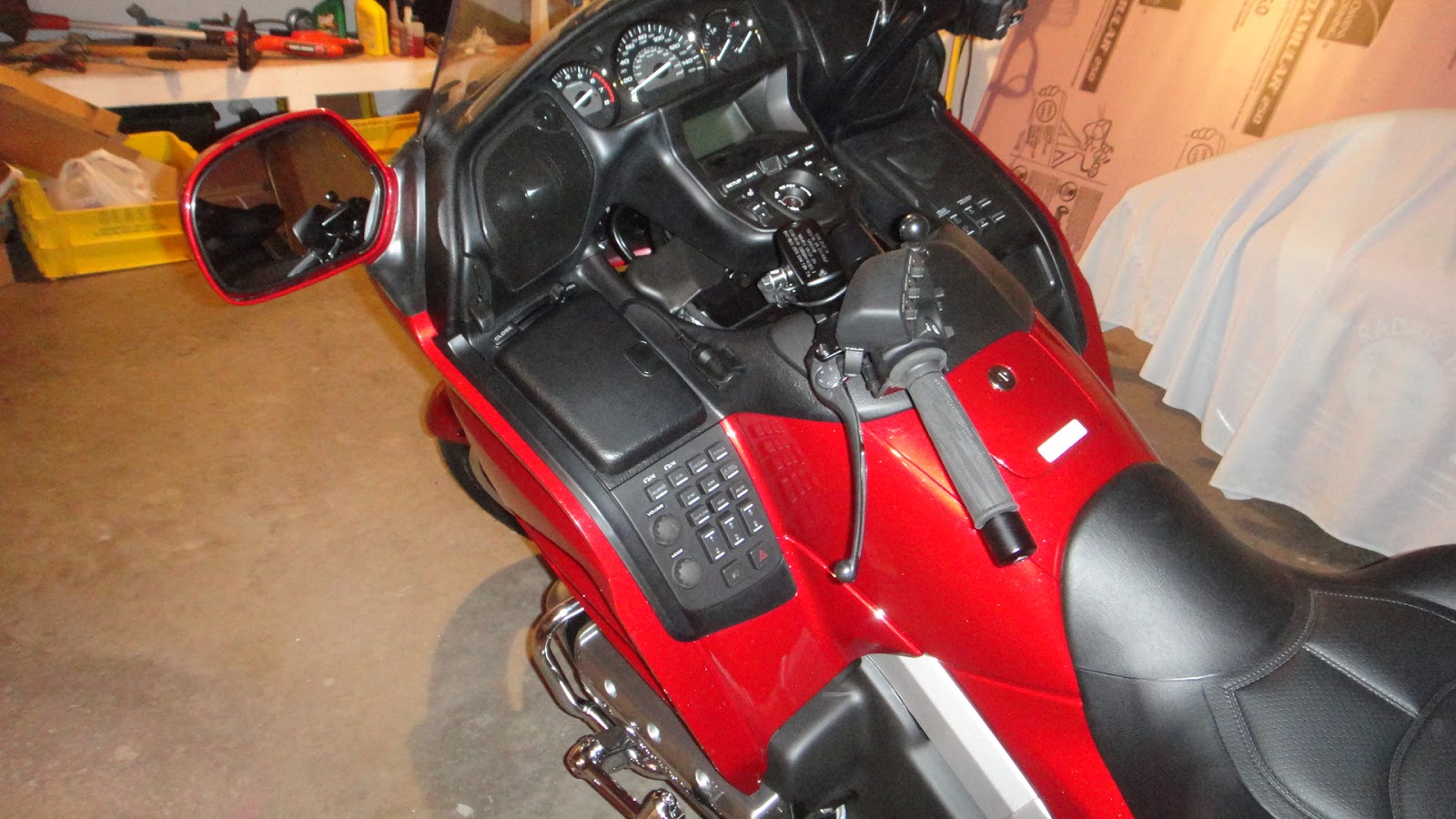
The first order of business for the bike was to figure out where to connect up power to the GPS. In the photo above you can see a panel with a lot of buttons on the left side of the bike. This is the audio setup for the Goldwing. Just ahead of that is a storage compartment with an access door to get into it. Underneath this storage compartment is a set of power connectors for accessories such as a power port that is mounted into the storage compartment or a USB port plugged into that same connector. A lot of guys that want a GPS mount for the Goldwing plug into this internal power port and do what my dealer had suggested. Cut a hole underneath the access door so a power wire could lead to the outside GPS. Again I think this is a terrible idea just for looks alone much less causing actual damage to a beautiful new motorcycle. Rather than take this drastic way of getting power to the GPS there had to be a better way.
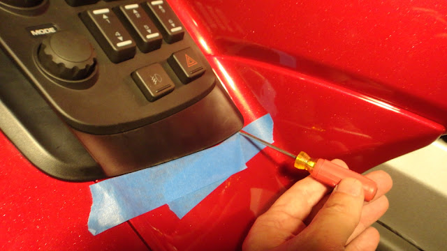
The first thing that needed to be done was to remove the storage compartment on the bike so I could get access to the power ports underneath. I taped off the lower edge of the body of the fairing on the left side of the bike and took a small screwdriver and pried up the "L" shaped trim that ran along the base and outer edge of the fairing.
This turned out to be the easiest part of this process as the trim popped off within 30 seconds! Even my dealer did not know that this trim needed to be removed first to get the storage compartment out.
Next I just needed to release the push pins in each corner of the storage compartment. In the photo above I am pointing to one of these fasteners. There are only four holding the storage compartment in place (one at each corner). To unlock the pins I took a paper clip and pressed down on to the center of the pin. It clicked inward about a 1/4". This unlocked the pin. I did the same with the remaining three pins and I was able to easily lift out the storage box with it's attached lid. You have to be careful with doing this so as to not pop the pins out and loose any of them. They were needed to get the storage box locked back into the bike when it came time for reassembly.


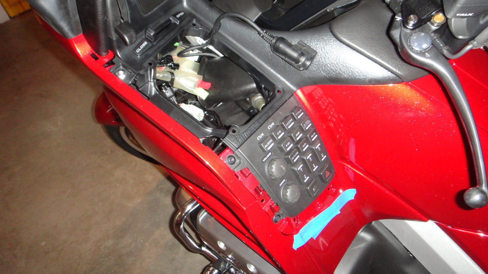
Now with the storage box completely removed you can see the wiring that is in the left side of the fairing. Standing out in this compartment you can easily see the red power connector that I needed. This is where I as going to get my power from for the GPS. Simple to connect to and right in plain view. If this connector was not there I would have had to try and route the wiring all the way back to the battery fuse box. Goldwings have a special port for accessories at that location to hook up things like a GPS but getting wires to it I feel would have been a total nightmare to accomplish. Not my idea of a fun thing to try and do.

My next plan of action to start the wiring for the GPS was to be able to connect to the red power outlet under the storage compartment. The easiest way I found to get the right connector was to buy a power port that usually mounted to the inside of the storage compartment. Since I did not plan on going this route I only needed the wiring harness from the power port so that I could easily plug it into the red power outlet underneath the storage compartment. This gave me what I needed to accomplish this part of the project.

I took the wiring with the correct plug for the red power outlet along with the wiring that came with my Garmin GPS to my local Radio Shack. There one of the employees helped me find the correct connectors that matched what was on the power outlet wiring. Then added mating connectors to the Garmin GPS wiring so the two could be plugged into one another. Now I had a wiring harness that would plug directly into the red power outlet and could be plugged directly into the GPS. With the red power outlet power is only supplied when the bike is either turned on or turned to accessory. This eliminated the chance that the GPS would run down the battery if the bike was turned off.

Next came the tricky part of the project......routing the wire from inside the fairing to the outside to get to the handlebar mounted GPS. I looked closely at the inside of the fairing as well as the area underneath it and found a couple place where the wiring could be snaked through to the outside of the fairing. To get it there I took a small stiff plastic tube that I had in my shop supplies and taped the wiring to the end of it. This white tube was around 16 or 17 inches long. In the photo above I started sliding the tube down inside the fairing to a opening that I could see on the bottom. Not a lot of room but it looked doable to get the wiring through to the outside.
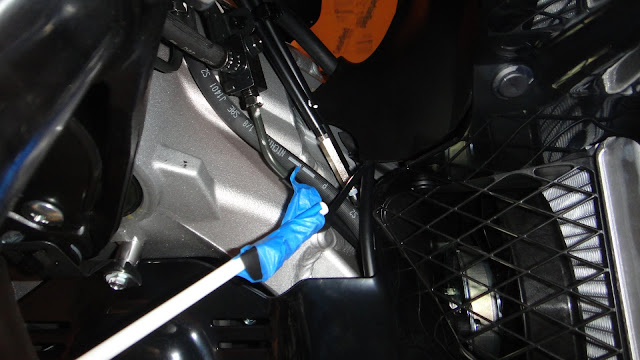
Here's a shot of the plastic tube again from the underside of the fairing just behind the front wheel of the bike. On the lower right side of the picture you can see a plastic mesh covering one of the radiators for the bike. Just above the blue tape and to the right is a black area. This is the bottom cover just underneath the wiring that is underneath the storage compartment. There was enough space between this black cover and the frame to get the wiring snaked through to the outside of the fairing. The area that the wire now was being fed into is an open area that surround the handlebars in the fairing.
I removed the plastic tube and the blue tape and now you can see the GPS power connector that I lit up with my flashlight to get the photo you see above. At this point I was on the downhill slide of making this installation actually work.
I had to bring this photo back up again to explain the next step. The wiring for the GPS now was being installed into the open area on the left hand side of the handlebars. I routed the wire to the center of the handlebars or as close as I could to get it in a safe location to be routed through the left handlebar. I will explain this process in a minute. I left enough slack in the wiring in this open cavity that the handlebars move in to steer the bike so that the wiring would not get pinched or snagged on anything while I was driving. I secured the wiring with zip ties in a couple locations and within a few minutes was happy with the routing and moved on to the next step.

On the Goldwing the handlebars are filled with wiring and hydraulic lines. These are coved up with small plastic covers to contain and clean up the look of the motorcycle. I pulled the cover off the left handlebar so that I could route the GPS wiring through it. There was just enough room to accomplish this part of the assembly but the screws are a bit tricky to get back into place once they have been removed. If you plan on doing this with your Goldwing I suggest covering up any open areas of the bike before you do this. If you drop a screw you will be lucky to find it again as it will either drop on the floor or into the now open fairing. I took my time and was lucky enough to get everything pulled apart and routed inside the handlebar and then buttoned back up again. Luckily a Philips screw driver is all I needed to get the cover off or put it back on again.

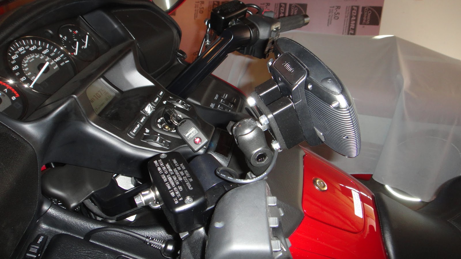
Now with the GPS wiring nearly done I mounted the Ram mount next to the audio volume controls on the left handle bar. This was very easy to do with the mounting hardware supplied with the mount. I removed a couple of screws at this location, added the new mount with longer hardware and it was done. The mount has a rubber coated ball on the top of it for mounting everything from a GPS to a GoPro camera. I left enough wire for the GPS so that I would not have any issues with connecting it to the unit when I needed it. This is a simple small mount that does not detract from the look of the bike when this is mounted by itself. Note: Keep this in mind as you progress further in this post and you will understand why I am modifying this mount.
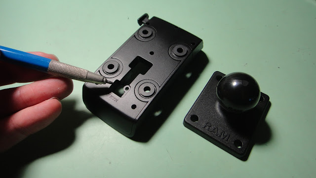
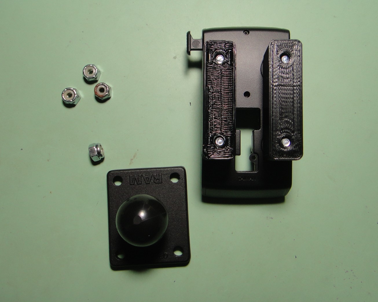
At this point I started looking at the mounting assembly for the GPS. This model of GPS from Garmin has a quick release mount for the GPS so that it can be removed from the bike when you are stopped while on your travels. This way you can lock the GPS away or take it with you and not have to worry about getting it stolen. I liked that idea but found that the rest of the design for the mount was lacking in planning when putting it on or taking it completely off of the motorcycle. In the photo above you can see the back side of the quick release mount for the GPS. The open area that I am pointing to is where the GPS power plug is installed into the mount. The plug gets pushed through the upper portion of the opening and then slide down and locked into the lower portion. Next to this mount is the Ram mount that will be mounted to this quick release mount. This is where it gets a bit ugly.
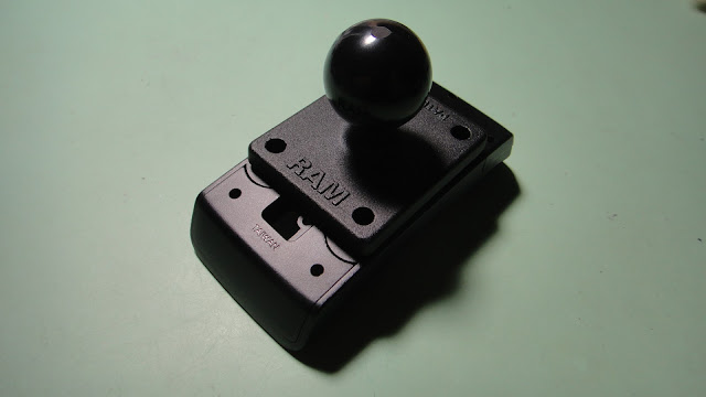
With the Ram mounted bolted to the quick release mount and the power wiring locked into the lower portion of the opening this mount now will have to be assembled and disassembled every time you want to put this part of the assembly on or take it off of the bike. The only other choice is to leave this mounting assembly on your bike all the time even if you are not using the GPS. Not what I wanted at all. It looks completely ridiculous to have this mount on the handlebars when you are not using the GPS going down the road. The ball on the Ram mount makes for quick and easy assembly or disassembly but the wiring is still tied to the setup. Not a good idea. I want to take the complete assembly off of the bike quickly and easily when I am not using the GPS. It's just a simple fact that no one especially me uses a GPS every time when riding a motorcycle.
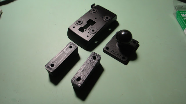
To get around all of this hassle I took a look at the mounts and the wiring and came up with this solution. I 3D printed two 3/4" spacers that will eliminate the hassle of having to take this assembly apart every time I want to remove it from the Goldwing.
With the spacer in place the Ram mount now can sit on top of the assembly and still allow access to the wiring when the assembly is dismounted from the bike.
The opening for the wiring now is free and clear so that the wire for power can be slid into place just as easily as before but will not be hampered by the Ram mount when it is in position in the assembly.
The spacer being 3/4" thick allow enough room for the end of the power wire to be fed into the opening just under the Ram mount. Kind of like a snake running through a tunnel when the assembly is put together. It's just big enough to get you finger in the opening of the tunnel to shove the wiring down through the opening in the GPS mounting plate and lock it into the lower position in the opening I spoke of earlier.
Here is what the GPS mounting plate looks like from the front with the power wire and it's cover in their respective locations. The power wire contacts are on the bottom to match up to the contacts that are on the back side of the GPS when it is locked into position for use.
An underside view of the GPS mount with the wiring, spacers, and Ram mount all assembled.
Here's a top view. You can easily see the tunnel I was speaking of to allow access to the installation or removal of the power wire for the GPS.
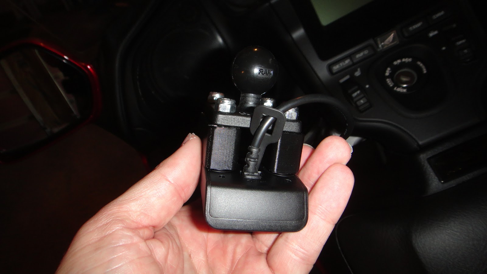
The picture above shows the GPS mount fully assembled sitting next to the double-socket arm. This arm easily attaches the GPS mount to the mating Ram ball mount that I installed next to the audio controls on the left handlebar of the bike.
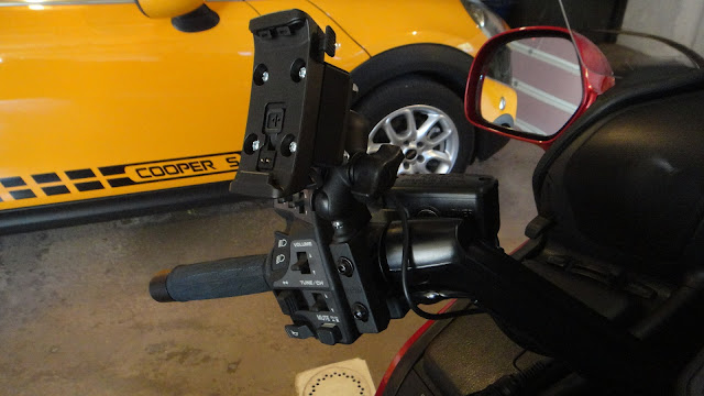
Here the GPS assembly is mounted to the Goldwing using the Ram mount. The double-socket arm between the two balls (one on the handlebar mount and the other on the GPS assembly) has a small knob that you turn to tighten the assembly to hold it securely in place. This is very quick and easy to do when you want to mount or dismount the setup. Plus now with my new adapters mounted into the assembly I am able to unplug the wiring and remove the entire upper assembly in a couple of minutes. In the photo above you can plainly see what I was saying earlier about leaving this mount on the bike when you are not using the GPS. Ugly in my eyes.


Then I slide the GPS unit into it's mount and it locked into place quickly and securely. Now all I needed to do was reinstall the storage compartment with the four push pins. You take the pins and move the center section of the pin so that it stands out of it's surrounding outer sleeve about a 1/4 inch or so. When you put the compartment back into place it's just a matter of dropping these pins into their respective locations and pushing down on the center of the pin until it clicks. Then it is locked once again. Then take the "L" shaped trim that I removed in the first step and click it into place starting at the upper front location and move on down to the lower horizontal location clips. It locked right back into place and only took me 10 seconds or so to secure it where it started from.
Now I have a GPS that I can put on to my Goldwing or take off in a couple of minutes without tools or having to disassembly anything in the process. When the bike does not have the GPS on it I only have the small Ram mount with the ball on the end of it mounted next to the audio controls and the power wire for the GPS. This wire I route around to the front of the handlebar and secured it with a small twist tie to keep it out of the way until I need it again. With the rubber cap that comes with the power wire plug it is also safe from any rain I might encounter along the way.
So that's it. A nice clean installation of a GPS on a 2016 Honda Goldwing. If you have any questions about the installation let me know I'll be more than happy to fill you in on anything I missed. Have a good day on your motorcycle and a better day on your next project.