Monday, January 27, 2014

Blender Cycles: Lighting and Rendering Cookbook Review


A few weeks ago I was asked to review the new Blender Cycles: Lighting and Rendering Cookbook pictured above from the Packt Publishing company. The following is my review of this book.


 After having worked my way through several of the first chapters of this book I have found it difficult at times to follow the instructions that are in it.  I have been using Blender for many years now and the instructions though well intended fall short at times with miss direction, missing information, or just a plain over assumption of knowledge and terminology to accomplish a procedure.  Either directions do not match illustrations, or information and files are missing to complete the steps needed to finish a project. Only with repeated efforts to complete steps on single projects was I able to finish the projects that I attempted to create.  The results were very good with this effort but would have been more rewarding had there been more precise, accurate information and illustrations to go along with the information given.  I looked forward to learning new things using Blender 3D and enjoying the process along the way.  Instead I found it to be a struggle just to get through the first couple of chapters because of the manner in which the information was presented.  This is definitely not a book for a first time user to create anything using Blender.  If you have no knowledge of Blender 3D basics this book will be of no use to you.  Even if you have used Blender for a number of years as I have be prepared to start learning all over again….. slowly and not easily.


Thursday, January 23, 2014

3D Printed IPad Video Teleprompter Project


Here's my latest creation from the Tinker's Workshop that I just completed yesterday!  It is a 3D printed IPad video teleprompter.  I've always wanted one of these and I finally came up with a design that fits the bill and my budget.  When I have put together video presentations for the blog in the past, most of the time it takes me what seems to be hours just to get my introduction and explanation of a project down good enough to call decent video.  With this teleprompter it has simplified that whole process tremendously. 
  I have been thinking about this project for some time and finally got it all together in just a matter of a few days.  A very quick build to say the least. 


   The entire unit cost less than $30 to make and works great.  For more information about this great project check out the video presentation that is posted here.  Also for those of you who have access to a 3D printer and are in need of this type of equipment for your video productions I have a complete set of plans and 3D printer STL files for only $5.00 available now on my plans and STL files page here on the blog.


  Check out the video below to see how it all goes together. 


Thursday, January 16, 2014

Giant Lego Gyrocopter Man Project Completed!


After a little over 100 hours of work I completed the Giant Gyrocopter Man project this morning!  This has been a great project and I am thrilled with the end result. 


The assembly of the pilot went very smoothly so I was able to call the project done this morning once I had placed him in the gyrocopter seat.  The overall size of the gyrocopter is 23" long, 9" wide and 14" tall at the mast.  Check out the video of the entire project and you will see how all of the 161 parts of the build were assembled.  


This photo says it all.  The pilot for the gyrocopter is huge compared to a regular Lego man.  The pilot stands almost ten inches high and weighs a little over a half a pound.  He took fifteen and a half hours to make using a Makerbot Replicator 3D printer. 

Here's the video of the assembly and more photos of the entire project. Enjoy the photos and the video!

Saturday, January 11, 2014

More Parts For The Giant Gyrocopter Lego Man Project


The hours have been adding up quickly now with the progress I have been making on the Giant Lego Man Gyrocopter project.  I thought it best to get these photos out to show you how it is all coming along.


This is the fuel tank assembly that will be mounted into the gyrocopter just behind the seat.  The entire assembly measures 2" deep, 3" wide, and 4" tall.  I like the detail that is in the fuel tank of the recessed portions of the tank along with the little yellow fuel cap.


Here is the seat assembly ready to be mounted on to the main frame of the gyrocopter.  I had moved the control stick to the center in front of the pilot instead of it being mounted on the side like the black throttle handle that you see here.  The recessed area of the seat is designed so that the Lego pilot will not slide off of the seat when he is in position.  Dimensions for the seat assembly are 4" wide, 4.5" long and 5" tall.  So as you can see from those numbers the entire gyrocopter will have some big overall dimensions.  I like this fact because it it easy to get some nice detail in the individual sub-assemblies. For example.... the control stick is made from three separate pieces with the main shaft being aluminum.  Gives the stick a nice look.


Speaking of detail this photo shows all of the components that make up the instrument panel for the gyrocopter.  The panel on the left is 2" x 3" in size with six 3/4" recessed circular areas for each aircraft gauge.  These areas were painted white to start.  On the right side of the photo you can see some of the gauges yet to be cut out for the panel.  The images of the gauges were copied into my computer and then scaled down to 3/4" each in size and printed in reverse on to plastic that is used in an overhead projector.  Once the gauges have been cut down to the correct size they are inserted into the recessed areas of the instrument panel face up.  With the printing done in reverse the ink of the image is on the inside of the gauge instead of the outside face where it could be rubbed off over time. The black rings are then inserted on top of the plastic image to hold it all secure.


A great look for the instrument cluster once it has all been put together.  The face of the instrument panel was then glued on to the instrument pod to complete the nose section of the gyrocopter.  This process I will keep in mind if I ever make another model that will need gauges as the look is perfect for this application. 
  The gyrocopter at this point is nearing completion but I will hold off at this point in showing that completed assembly until I can get the Lego man pilot 3D printed and assembled.  You'll just have to wait for the grand unveiling once I get the complete project done.  Until then enjoy these photos as the end of this project will not be long in coming.  

Monday, January 6, 2014

3D Printed Engine For Lego Gyrocopter Project


Another very cold day here at the Tinker's Workshop so the order of the day is to continue working on the Lego Man Gyrocopter project.  I spent most of yesterday just printing parts for the engine and finishing up parts for the wheels so today I assembled everything for this post to show you how it all went together.


This is just one half of one of the wheels.  It has two of everything that you see here to make up an entire wheel.  All of the parta are then snapped together and the two halves are then sanded smooth where they meet and are glued together using regular modeling glue.


This is all three wheels once they have been assembled.  I really like the yellow and red as it a nice bright combination for the project.


This gives you a good idea of the scale of the model with one of the rear wheels in my hand.


Here are all of the parts that were needed to put the engine together for the gyrocopter project.  29 parts in all.  Starting at the upper right corner are the velocity stacks.  Then the engine block which took four hours alone to 3D print.  The silver and black pins are locating pins for the cylinder heads. To the left of these parts are the carburetors.  Just below them are the black exhaust pipes which will be glued together to make a tubular shape for the pipe.  The two yellow peanut shaped parts are the valve covers and again to the right are yellow elbow shaped pieces that will make up the carburetor tubes.  The last four black finned pieces make up the cylinder heads. 


Here is the assembly of one of the cylinder heads.  The silver cylinders are 1/4 aluminum rod that is mounted between two halves of the cylinder head.  I needed to add a small strip of black tape to the rods as my holes for the rods were just a little to large.  The tape solved this problem and saved me from having to reprint the heads. The two halves of the cylinder hears were glued together using plastic glue. 


Next the velocity stacks were glued into place on the carburetors.  I had to print the carburetors in two pieces as this was the simplest thing way to go to get the shape I was looking for.


I then added the valve covers to the cylinder heads and mounted them to the engine block.  The protrusion on the end of the engine will be where the propeller will be mounted on the gyrocopter.


Now the engine is starting to take shape with the carburetors mounted to the assembly along with the carbureator tubes.  I really like how everything fit up so nicely.


The last thing to install on the engine other than the propeller was the exhaust on both sides.  The engine at this point is 3 1/2 inches long, 4 1/2 inches  tall and 5 inches wide. 


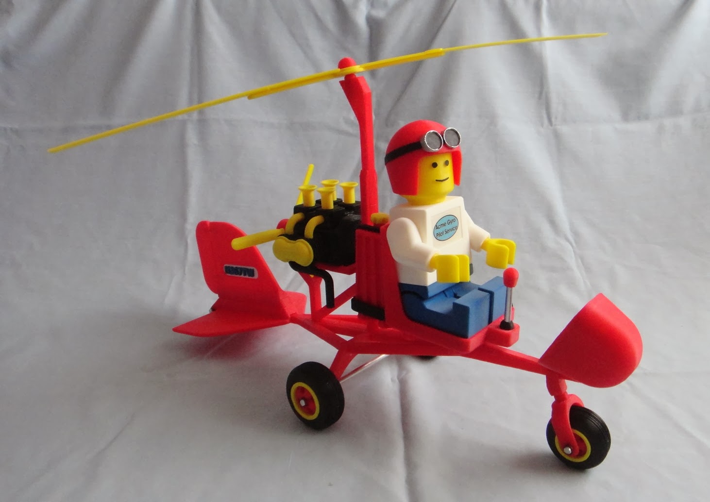
Now with the six inch diameter three bladed prop the motor really stands out for the project.  I only have to mount the engine permanently to the gyrocopter and this part of the project is done.  Total hours on the project so far has now risen to 35 hours plus 108 parts and still counting. Time flies when your having fun and this is a good time for me.
I find with the assembly a couple of issues that I may have to look at in the coming days.  One is the main axle for the gyrocopter itself.  I had to re-glue one of the aluminum pins for one of the main wheels today as it did not hold properly.  Hopefully I'll have the problem fixed in short order and I can move forward with the project.  If not I will have to do a bit of redesign to work out the problem.  Like anything else in design changes are expected.  Hopefully this will not be a big problem but you just never know.  So far the progress is steady and the results especially for the engine and the rest of the build have been worth the effort once again.  Stay tuned for more updates and enjoy the photos.

Thursday, January 2, 2014

Giant Lego Gyrocopter Man Build Progress

The last couple of days have been the perfect time to continue working on my giant Lego gyrocopter man project with all of the COLD weather that the Midwest has been enduring these past few days.  To stay in my nice warm computer room and print 3D parts most of the day sure feels good.  So with that in mind here is my progress so far.


I started with the tail feathers first as I thought this would be the most difficult portion of the build.  Hopefully at this point I am correct is saying so.  The photo above shows the vertical stabilizer for the gyrocopter.  The goal for this portion of the build was to figure out how to put the aircraft numbers on to the tail.  I did not want to create a decal as I wanted something with a bit more detail in it.  I instead designed an opening in the stabilizer that the number plates could be inserted into.  Also the original design had the rudder attached to the stabilizer when it was to be printed.  This simple would not work and get the effect that I was looking for.  So I opted for two small metal pins that the rudder would be mounted to.  The next question is what to use for pins.  Another brainstorm came about as I used a large paper clip cut to size.  Just heavy enough for strength but still small enough to mount easily.


The rudder pins are glued into the vertical stabilizer and then the rudder is slid on to the them with mating holes.  With the number plates glued into place the look works and is an easy part of the assembly.


Next the horizontal stabilizer for the tail was printed.  This was glued into a matching channel at the bottom of the vertical stabilizer.  You can see the additional channel in the assembly above that this assembly will mount to the framework of the gyrocopter.


Here is a view of the tail assembly mounted onto the gyrocopter frame.  The structure just forward of the tail assembly is the engine mount.  


This is a good overall view of the gyrocopter at this point.  Total hours to print what you see here has taken just a little over 13 hours not including assembly or design time.  For design time I can only guess at this point that the hours have to be around 25 or 30 hours time.  So I put a lot of thought into my designs before I even start making the first part. The gyrocopter framework as you see it here consists of 42 separate pieces that were pinned together in various places using 1/4 inch aluminum rods and regular plastic glue for models. Size of the assembly at this point is 12 inches tall, 21 1/2 inches long and 6 inches wide.  This will only get larger as I add more parts to the assembly. The machine screw at the top of the mast will mount the main rotor and allow it to spin freely.  
  I am very happy with the progress that I've made and the alignment of all of the parts for the assembly turned out very well. Next I will work on the wheels and axles that need to be mounted.  Luckily there are only three separate wheel assemblies that need to be made so it should be a simple task for the project.  At least that is what I am hoping for anyway.  Enjoy the photos.