Saturday, May 26, 2012

Out With The Old...... In With The New!

It's been a busy couple of weeks here at the Tinker's Workshop.  I thought it best to finally get a new post out on what has been happening and what is planned for the coming weeks.  I have been busy with a large project here at home that has turned into a chain reaction of projects as most people know can happen.  For some time now I have been wanting to replace the carpet in my bedroom and repaint the room at the same time.  This in turn called for the removal of a well cared for king size water bed which because of its weight had messed up the position of the closet in the bedroom.   The bed weighed close to 2000 pounds and had managed to shift the closet away from the back wall of the bedroom.   This I corrected with some help from a close friend and have now painted the bedroom and am waiting for the new carpet to be installed.  So now on to the fun part of this project.


  The current project I am now working on is to build a new bed to replace the water bed.  I no longer want that much weight on the floor and so I've decided to build a queen sized platform bed instead of the over sized, overweight king sized water bed.  This will be lighter on the floor and make more room in the bedroom too. The headboard of the water bed is solid oak and is to nice to discard and so that is where I started this project.


With this in mind I had to design a new platform bed using the king sized headboard yet still reduce the size of the new platform bed to a queen.  This is what I came up with.


The new platform bed will use a setup very similar to the water bed as it will have a base that the mattress and mattress deck will sit on.  A couple of things had to be addressed here in this project as the headboard is set up for a king sized bed and the mattress is a queen.  Also the headboard could not sit directly on the same platform as the mattress as it would be to low to be usable.  I designed a headboard riser that would straddle the platform so that the width difference from a queen to a king sized bed could be used along with raising up the headboard to a correct height. 


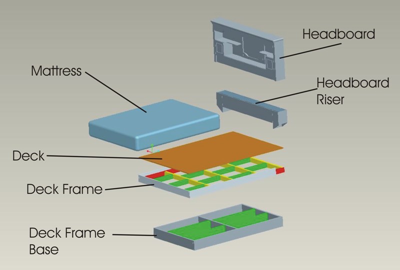
The headboard riser will be made from oak along with the mattress rail  (shown in gray) that will rap the deck and deck frame.  The deck frame base will be made out of 2 x 8's and the deck frame out of 2 x 4's. Both made from pine. The deck is half inch plywood.  All of the parts for the new bed now have been cut  and being as photos of a pile of wood is not that interesting I will hold off with taking more photos of the project until it starts taking shape.
   I was also concerned with the height of the bed mattress once the bed was completed as I thought it might be to low.  This turned out to be no big problem as the mattress is 12 inches thick and the total height will be 24 inches tall.  Very good news for the project.  I will post further photos  in the coming weeks as progress is made on this project.

Wednesday, May 9, 2012

A Video Camera Mount For Your Car For Less Than $20.00!

Today I completed another small project that has been in the back of my mind for some time now.  I've always wanted to take video in my Mini Cooper while cruising down the road.  That's what today's project is all about.  


These two photos show the wooden parts that were cut out on my CNC machine for the camera mount.  This could also be made using a band saw or scroll saw and a drill press just as easily.  


In these two photos you will see the remaining parts that are needed for the video camera mount.  There are two pieces of 3/4" poplar wood, two 1/4" x 3" bolts, four washers, two lock washers, two wing nuts, a 1/4" x 1" bolt and washer and a quick connect mount for the video camera.  The two small grooves in between the two horizontal arms will located the mount securely when it is put into the car for use.  The three inch bolts and related hardware squeeze the two wooden part together to create a strong simple mount that is as easy to use as it is to create.


Here is a good shot of the video camera mount located on the vertical posts that secure the headrest on the passenger front seat.  The seat needs to be in a near vertical position so the video camera is not pointing upward toward the roof.  I did a trial video using the mount on the passenger seat but found that  I liked the drivers seat video better. As long as the roads are fairly smooth the video turns out very well.  Check out what I shot  today for yourself. 


Click the YouTube button for a bigger view of the video.

Wednesday, May 2, 2012

The Second Steadicam Is Completed!

This past week I was thrilled to finally find in my mailbox the last piece that I needed for my second Steadicam that I started work on in mid April.  This critical piece was the adjustable mounting plate for the video camera.  Without it I could not complete the build of my new design.  For those of you who do not know what a Steadicam is or what it does for video I will clue you in.  This device takes the roughness out of video being shot while hand holding a video camera.  It was first used and developed for the movie "Rocky".  Since that time you have seen the end result of this device in scores of movies.  Most commonly used where a camera is following or leading an actor down the street and the director wants a smooth flowing shot without the camera bumping up and down from the cameraman's movements.  These professional devices are VERY expensive and just now have started to show up for the amateur videographers like myself.  So with that in mind I decided to build my own Steadicam this being the second design.


With any new design there are always bugs that need to be worked out of it.  This design was no exception to that rule. The picture above shows the upper mounting portion of the acrylic arm as I first designed it.  It looks good but that's about as far as it goes.  It simply did not work when mounted to the adjustable "C" shaped slider video camera rail.  I could not get the arm to balance and so a redesign was called for. The first arm being made out of fiberglass did not have the mounting hardware that you see in this shot.  This in turn caused the arm to be mounted further rearward on the slider rail.  This also caused an interference problem that would not allow me to make proper adjustments to balance the Steadicam.  
  What I did to correct this was redesign the original spacer mount that you see here with a modified spacer that has an extension on it to allow clearance for the balance arm.  Once this was done I cut it out the new part on the CNC machine and with a bit of sanding was ready to mount it. The original fiberglass arm on the first design was narrower and could be mounted on to the slider rail without the use of a spacer. 


Here are a couple of shots of what the new upper mount looks like in place on the Steadicam.  The extension on the new mount allows for an additional clearance both vertically and horizontally as the slider is adjusted to balance the Steadicam with the camera mounted to it.


Here is a good shot of me holding the new design which gives you a good idea of the size of the Steadicam.  This completed arm took around two hours to construct using my CNC machine to cut out the balance arm parts. Then came sanding, polishing, and assemble.  This is a vast improvement over the fiberglass design as it took around eight hours to build over a weeks time. The cost is higher on this arm due to the material used but in the long run will be much easier to fix should something catastrophic happen to it. (I don't even want to think about it!)  


For a larger view press the Youtube button.

Here is a little video that I put together this morning showing you the difference in what the Steadicam can do for your camera work. Keep in mind here that I have only had about a half hour of practice using this new Steadicam so I am no expert when using it yet.  But just with what I have shot here is a vast improvement over the video shot without using it.


  For those interested in the numbers.....  The original fiberglass design cost around $40 to build.  This new design is closer to $80 to build.  Both turned out well and both had their advantages and disadvantages in the building of them.  I for one like the new design simply because of the ease of construction, less build time, and easier repair.  If you had to repair the fiberglass design or replace it due to major damage it would take another week to build a new one.  This design you could salvage all the good parts and only replace what needed to be to make it work once again.  A lot less time to do so.  All in all it will make a nice addition to my video camera equipment.