Friday, April 27, 2012

Free Design Software For Your Projects

  This past week I have been asked by a number of people how do I create the projects that I have posted on my blog and build in the workshop.  The first thing that I do with any project is set down at my computer and design all the components of a particular project in my engineering design software named Pro Engineering or ProE for short. This software is VERY expensive and way out of the reach of Joe Average's budget and so does no good for anyone that wants to eat meals on a regular basis. This software I used and was trained on at John Deere where I worked as a designer for over 20 years of my 33 year career.  I was fortunate enough to be able to get a student version of this software which fits my needs very well but someday I will have to replace with something cheaper when it no longer will run on my computer. This is all well and good for me but does nothing for the rest of my readers that have not had this kind of formal training or luck in getting this software in the first place to build the projects that they dream of making.
  Fear not.  I have some answers for all of you that I hope will get you off of the couch and into your workshop building your dream project.  In a lot of my projects I have also used three other pieces of software that are free to download online which will get you started.  The first program is called Blender 3D.  This is a great free software that you can use to concept your project to see what it will look like before you even start making parts.  Here's the link to their site.


I have been using Blender 3D now for around 15 years and have taught an introductory class at the QC Co-Lab maker space in Davenport Iowa.  As with any software it will take some time to learn how to use it to get you up to speed.  This really is not a big problem if you put the time into learning it.  There are a number of ways to accomplish this. First big thing is all the tutorials that are online right now for Blender 3D.  There are a number of forums  also that will help beginners with from day one to get you started. One book that I have picked up for my Blender library that I thought was a good tool is named believe it or not...  Blender For Dummies!  Yes this book is for real. I have it on my Ipad and it's just what a beginner needs to get started.  Blender also does animation, and game creation if you want to get into that also.  You can see some of the computer models that I have created by clicking the link at the top of this page.

  The second piece of software that is another good tool for creating your designs is named Google Sketchup.   


 Everything from furniture to automobiles have been modeled using this software. One of the good things about this software over Blender 3D is that the learning curve to create anything is much quicker and easier.  It does not have the polish and look of a finished Blender image but for the purpose of designing a project it does very well.  


Click the YouTube button to view this video larger.

Check out this tutorial on how to use Google Sketchup and you'll see how easy it is to use. 


The last piece of software that I am happy to show you which can do almost everything ProE software can do and still is free to download is called Creo Elements/Direct Modeling Express.  This software was created by PTC (the same company that developed ProE).  You can download it at this link.


http://www.ptc.com/products/creo-elements-direct/modeling-express/


The video below is one of many online that will get you started with this real CAD software that can help you with your projects. I like the interface much more than ProE's as it is quite a bit more user friendly to start out with.  With my discussions over the years about using and learning ProE my best description of the learning curve for this software is this.  It took me two weeks of training to just learn what buttons were what in the software, six more months of on the job training with a tutor that had the patience of a saint to put up with all my questions about the software that I had and then another twenty years to know what I was doing with it in the first place.  (After the first six month you only know enough to be dangerous.)  A VERY steep learning curve to say the least.  
  Creo on the other hand looks to be much more user friendly than ProE, this and the fact that it's free is at least worth looking at.  The tutorials that I have found online will go a long way at getting anyone up to speed using this software for your project designs.  The software will create working drawings of the parts that you'll want to make in your shop so that you'll not have to have your computer next to your drill press. Check out the video to see what it's all about then do more searching online for further tutorials on what you can make with this great software.


Click the YouTube button to view this video larger.

I hope this helps anyone out there trying to design and build anything in their workshop. I know I would be lost without my CAD software to guide and inspire my creative en-devours.   Makes life a whole lot easier while dreaming up my next big masterpiece. 
Thursday, April 19, 2012

Steadicam # 2 Progress

Another rainy day here in the Midwest so it's a good day to get something done on steadicam #2 in the workshop.  I received the one inch thick plastic in the mail yesterday that I needed for the spacers designed for this project.  So follow along below and you'll see the steps I took to put the new steadicam arm together.


The plastic that I used for this project is a slab of white plastic that is used for a cutting board in your kitchen.  This piece is eight inches square and one inch thick.  A nice piece of material to work with.  I ordered this item from a company called freckleface.com online.  This is one of the smaller pieces which was  perfect for this project at a really cheap price too.  They have this material in sizes all the way up to three by four feet.  They also have a  lot of other products that I will keep in mind  when I work on new projects.


  I always make a test cut of a new part in foam before I cut the real thing.  Saves a lot of time, effort, and disappointment in making new parts.  This is the lower spacer for the arm cut from the plastic slab.


All three spacer parts cut out and cleaned up after the CNC milling. 


Here all of the parts for steadicam #2 are ready for assembly.  The arms themselves are cut out of clear 1/4 inch thick polycarbonate plastic.  This only took around ten minutes for each arm. Also in the photo are the spacers, washers, 1/4 inch threaded rod connectors, and allen head 3/4 inch long bolts.


The threaded rod connectors are slid into the holes in the spacers.  These worked out very well and were a good friction fit.  The connectors were used instead of just a bolt running through the assembly so that both sides of the arm matched when the allen head bolts were installed. This gives the arm a good clean finished look once everything is in place.


Here the spacers are attached to the two arms using the allen bolts on both sides of the assembly.  Everything in the assembly lined up perfectly like it was designed to do.  I breathed a sigh of relief. 


Here are a couple of good views of what the upper and lower mounts for the upper platform and the lower weights look like.  The allen head bolts really look good in the assembly.  The arm at this point is ready for assembly to the video camera platform and it's related hardware.  I would do this if I had the platform.  As usual I am waiting for it and other components to be delivered in the mail. I suspect them any day now.  Once I do receive them I will show off the completed steadicam #2 in another post.  
  Total time to put steadicam #2 together takes around two hours time to machine the parts on the CNC and assemble.  A vast improvement over the first steadicam that took four times longer to make.  
  At this point of the build I am very pleased with the over all look of the new arm.  In an earlier post I said that I was not sure if I would keep the clear polycarbonate arms or if I would go to aluminum.  Aluminum is out simply because of the cost.  Much higher cost just for the look. The polycarbonate arm look to be plenty strong with a good look at a cheaper price.  I also played around with the idea of making the arms out of the same material that the spacers are made out of.  This would be a possibility using 1/4 inch thick material.  Something to keep in mind if I wanted another option for this project if I build another one.  No matter what this project is getting high marks already on my smile meter!

Tuesday, April 17, 2012

Another New Steadicam Design In The Works

This week spring has sprung in a big way here in the Midwest and so like everyone else at this time of year there are a lot of chores that need to be done and some are fun and not so fun.  I had to mow my lawn today for the first time this season which looked more like a jungle before I started.  This was not so much fun but at least I have a small yard so it's not as bad as it sounds.  I also got my motorcycle out of winter storage and put my carefully charged battery in my Honda Goldwing and off to the motorcycle shop for a spring check-up, oil change and new tires.  This was the fun part. At least until I see the bill for the work that needs to be done. These two chores along with other spring activities have slowed my progress a bit in the workshop. 

The first steadicam design.

  So to the point here I have been working on a new steadicam design / build.  If you have been following my blog your next question I am sure is "Why build another steadicam?" I have had a lot of email about my last build of the fiberglass steadicam from a little while back.  The steadicam turned out better than I had hoped and had a great response about the design. The reason I am building another steadicam is because I sold the first steadicam to a filmmaker in Barcelona Spain for a good price and so this design was born from what I learned the first time around. The drawback with the first design was that it took roughly eight hours to build the arm out of wood and fiberglass. Glass and let it dry, glass some more and let it dry.  Sand and prime, and sand and prime. Then on to paint over and over. So you can see what it took to build.  My new design is a lot more streamlined with less work to build.  Here are some Blender 3D graphics of the new design.


These first two images of of the new design uses polished aluminum.  A great look to be sure but with drawbacks that I will explain in a minute. The arm is identical to the original design in shape with the addition of a double arm and spacers between them. I love the look of the polished aluminum and have yet to decide if this is the way I will go on the final build. The aluminum is 1/4 inch thick and being this thick it will be plenty stiff for the arm but with that thickness also comes the weight.  The volume per arm is 4.63 cubic inches and with aluminum weighing 1.56 ounces per cubic inch comes to 14.44 oz. for both arms not including spacers , and hardware to mount it.  Not sure if I want the arm to be that heavy.  It's a trade off to be sure. 
  I've also played around with the idea of building the arms for the steadicam out of carbon fiber.  This would be an outsatnding look for the steadicam, be super strong, and very light weight.  This all sounded good until I checked out the price for 1/4 inch thick carbon fiber panel bigger enough to make the arms out of.  A piece 12 x 18 inches comes to a whopping $175.  OUCH!  Even if I only go with 1/8 inch thick carbon fiber parts it will still cost way more than I want to spend on this project.  So that idea was scrapped early on.


These two images show the same design but using polycarbonate plastic instead of aluminum. This plastic is the same material used in bullet proof windows. It would make the arm a lot lighter than aluminum and much cheaper than carbon fiber. Not as strong as the other two materials of course but still looks great and is stronger than normal plexiglass just in case of an accident where it might get dropped.  (Heaven forbid!).  I have the polycarbonate arms already cut out on the CNC machine in the workshop but until I get the spacer material I will wait for further photos here as it will be simpler to show and explain the new assembly. 
  Every thing else on the steadicam is the same as my original design and should only take a couple of hours to assemble.  A big plus compared to eight hours of fiberglassing, sanding, and painting.

    I'll post more photos of this build once the last of the parts for the steadicam show up in the mail and I get the spacers machined in the  workshop.  Until then I will be out on my motorcycle enjoying the warm spring weather cruising down some favorite back roads and planning a big motorcycle trip for the summer.


Saturday, April 7, 2012

The Indian Motorcycle Light Display Is Completed!

With the help of my friend Steve Hamer at the QC Co-Lab maker space today we completed the assembly of the Indian motorcycle light display that I have been working on.  But first the light base assembly had to be cut out on the CNC machine this week in the workshop.  

  This photo is of the 1/4 inch thick poplar top and bottom pieces (right side of photo) and the 1/2 inch thick poplar mid-sections (left side of photo).  I chose poplar simply because of the light displays that I had made for my sisters last Christmas.  A nice wood to work with and I simply like the look of it once it has been varnished.

The bottom piece and the two mid-section pieces are glued, stacked together and then clamped.  This will make the cavity needed for the electronics to light the display.


Once the glued assembly has dried the bottom piece is added to the assembly using wood screws that have been counter sunk.

 Here the assembly has been sanded by hand and with the help of a drum sander on my drill press. Next five coats of varnish will be added to put a good finish on the base. 


This photos is a good daylight shot of the display showing the detail in the engraving and how the light box looks after it has been varnished. I like the light color of the poplar wood.  Nice and bright.  Next the internal electronics, light, and power switch are added. The power cord and on off switch are mounted through the back of the wood base to make for a cleaner look once everything is in place.

This is a reprint of the photo of the internal electronics for the Angel display that I built last Christmas but it is exactly what is now in the Indian motorcycle display.  I simply did not get a photo of this view while working on the Indian display today.  The only thing missing in this shot is the power cord that comes into the cavity alongside  of power switch. 


These last two shots give you a good idea of what the display looks like in a couple of different lighting conditions.  The top light is with room lights on and of course the bottom photo is of the display on in the dark.  Makes a great night light!  Either on or off the Indian motorcycle is a great display and will make a nice addition to almost any room in my house.  

Monday, April 2, 2012

CNC Engraved 1912 Indian Motorcycle On Acrylic Plastic

Here is another project that has been on my mind and the back burner for some time now and it finally came together for me today in the workshop.  This engraving is of a drawing that I had done a couple of years ago. As usual having other projects ahead of it I let it sit on my to do list way to long. That all changed today. 


The engraving is of a 1912 Indian eight valve board track racer.  I always liked the drawing I had done and am now the proud owner of this latest effort. The engraving is on 1/4 thick acrylic and is 6 x 10 inches in size.  The tab on the bottom of the engraving is there to allow the acrylic to be mounted into a box with a matching slot to receive it so that light will shine through the acrylic just as you see it here. It will make a nice addition to my computer desk don't you think?  One more thing to scratch off my workshop to do list and put another big smile on my face.

Sunday, April 1, 2012

NCSim.... A Free CNC 3 Axis Simulator You Can Download!

Push the YouTube button to view the video larger.

Here is a little video that I put together of a CNC 3 axis simulator called NCSim that I use here at the Tinker's Workshop.  Check out the video it will explain most of what I use it for and how you can get it for free for your CNC machine projects.   Here's the link for more information and how you can get the free software download.  http://www.cs.technion.ac.il/~gershon/NCSim/  Enjoy!

Solsylva CNC Machine Improvement Drawings

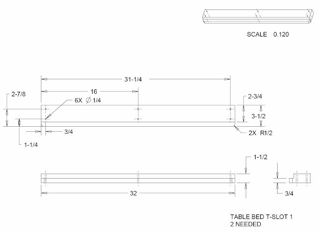
  I was doing some clean-up on my computer this morning and came across some drawings I had put together of the improvements that I had made to the Solylva CNC machine that is in the shop and that I have been working on at the QC Co-Lab maker space in Davenport Iowa.  These modifications that I had made to the machine allow for a usable "T" slot table and a stand for the machine that is simpler to construct.  Here are the detailed drawings of the individual parts and assemblies for anyone that would like them. 


  If you have not seen the videos that I have shot of the Solylva CNC machine build in Davenport please check them out in earlier posts on this blog.  It will show you these parts being built and how the assemblies are put together.  Lots of good info if you are interested in these modifications or just how to put a Solylva CNC machine together.  I hope you will consider using the designs in your build of a Solsylva CNC machine. I know I will update the CNC in my shop with these mods once the weather here in the Midwest gives me a good stretch of weather to do painting outside. Enjoy the drawings.