Thursday, July 25, 2019

The End.

Hello Everyone!

Over the past several months I have debated over and over again whether or not to continue with this blog.  Not that this process has not had it's positive points along the way or that I have had any bad experience because of my efforts.  Neither has been the case. In a few short weeks the blog would have been running for eight years.  A very long time.  

I have been watching the readership numbers go up and down over these past eight years with amazement over having had so many visitors along the way.  Over a half a million readers from around the world in over 100 countries.  In all this time I have never gotten a disrespectful or nasty comment from anyone about the postings I shared with all of you. That alone is quite an accomplishment in itself so I feel very fortunate in being able to say that.  

I had to go back to the postings just out of curiosity to see how many projects that I worked on over these past eight years.  The best I can figure is that the number comes up to roughly 125 different projects.  That averages out to a little over 15 different projects a year.  Again another nice accomplishment over that amount of time. 

All of this has been quite rewarding for me and I want to thank all of you who have followed along on this journey.   I hope that I have given at least some of you some inspiration, enjoyment, and laughter along the way.  With that being said I wanted all of you to know that this will be the last posting on the blog. I have had a great time and now am moving on to other interests.  It has been a great ride and I wish all of you good luck with your projects.  I hope that you will find as much joy as I have in creating something new in your workshop or have come up with a solution to a problem that has been driving you crazy for some time.  Thanks for all the comments and visits to the blog. All of you have made these past eight years worth every minute of effort in the workshop. Best wishes to all of you.

Sincerely,

Dave Langkamp
The Tinker's Workshop

Saturday, July 13, 2019

1/6th Scale 3D Printed 1927 Bugatti Type 35 Model Project Part 6

Back to work once again on the 1/6th scale 1927 Bugatti Type 35 model has produced a pile of parts and a lot of 3D printing to get to this point.  I had to look back on the last post I did about this project.  It was this last May.  Like most projects other things tend to put projects on hold due to other priorities. This has obviously been the case while working on this model. 


This is the finished design that I put together in Fusion 360 software.  This portion of the project has taken me at least 200 hours just to get the design worked out.  Hopefully I have crossed all the "T's" and dotted all the "I's" while working out the design.


Here is a good shot of some of the major parts that have already been 3D printed for the model.  


This is a good look at the floor of the driver's compartment.  On the left of the floor you can see the pedals for the driver.  Then more to the center is the transmission and the floor bracing.  Farther to the right are the seats without the seatback and then finally the bell housing for the rear axle.


A few more views of the frame with the rear axle, seats and floor of the model. 


The big news with this post is the completion of the 3D printing of the boat tail rear of the model.  This part is a very distinctive part of the Bugatti and took 44 hours to 3D print.  The image above shows you what the part looks like right off of the printer before support material was removed. 


Lots and lots of support material needed to be removed from this part.  I had to be careful not to break any of the supports for the frame that are on the inside of this part while removing this pile of support material. It took me an hour an a half to get the job done. 


Here is a closer look at the finished part after the support material had been removed.  I am really happy that the bolts that are on the body line worked out as well as they did.  It's a nice detail that will look good on the finished model. 


The hole on the top of the part is for the fuel filler cap.  I also am pleased that the louvers at the rear of the tail that worked out very well.  Another nice detail that will make the model stand out. 


 The boat tail section of the model is a pretty good sized part being 5 inches tall, 5.5 inches wide and 10 inches long.  With my cell phone sitting next to it gives you a good idea of how big it is.  The largest part in the entire model so I am glad that it turned out as well as it did. 

That's about it for this latest post about the Bugatti model.  In the coming weeks I hope to make more steady progress on the model.  The two rather large parts of the model that will be 3D printed next is the driver's compartment and the front hood.  Both of these are big pieces but I don't think they will take anywhere near as long to print as the boat tail has with this project. 

 A new record for 3D printing for me on this project having to make a part that took 44 hours.  I'll post more as I move forward with this project.  Should be interesting once I start putting everything together to complete this project.  Stay tuned for further developments. 


Thursday, July 11, 2019

New Dune Buggy Roof Installation Project

I was not sure if this post was going to get out at all after the events that had taken place over the past few weeks here at the workshop.  Some good events and some not so good.  The best event was the arrival of my new Mini Cooper.  As most of you already know and have read about, I am a Mini Cooper nut to say the least.  I had ordered a new Mini Cooper to replace my orange 2014 Mini and the it finally arrived last weekend after waiting two and a half months. 


 I am thrilled with the new car so that is always a good event. 

 The bad event that happened these past few weeks was a major storm that hit my little town.  Every tree in town either had some storm damage or had complete storm damage where the tree was knocked down and needed to be removed.  Two of my neighbors had this happen. I had more than enough sticks and branches in my yard that took three days to clear.  A pain to say the least.  I also have a tree that needs to be cut down not because of the storm but the fact that it is dyeing.  I was amazed that the 72 mph storm did not knock it down in the process as well.  So I am lucky in that respect anyway.  So that catches you up with things around my neighborhood so let me get to this weeks project.

I thought I was done working on my dune buggy with all the projects that I have done on it so far but with the installation of a new convertible top I was mistaken.  The top fit my dune buggy for the most part and installing it was not a real problem.  The one thing that I was not happy with the new top was how it fit the roll bar and windshield where you climbed into the car. 


You can see from the photos above how the roof does not quite lay right just above the driver and passenger side openings where you climb in with the top on. 


Part of the issue may be with the new installation of windshield clips that the roof snaps on to at the front corners of the roof.  Originally these snaps were designed to be mounted using metal screws that had to be mounted to the windshield frame by drilling holes into the frame itself.  Not something I thought was a good idea from the start. I designed this simple clip that mounts to the windshield frame and has the snap mounted to it so no drilling is required to mount it.  

When I mounted the new bikini convertible top to these clips it may have caused the issue with the roof not laying right on both sides of the car. I went to worn on the problem and came up with a solution that makes the roof even more secure while driving down the road as well as giving the roof line at the entrances of the car a nice look in the process.

I designed a support frame for both sides of the car that would be made out of a custom fit fiberglass panel, fiberglass rods, two 3-D printed end mounts that fit between the rear roll bar and the windshield and four 3-D printed curved fiberglass rod mounts. 


To make the fiberglass curved panels I made simple templates from my computer design of the part using Fusion 360 software.  From the computer design I printed out templates and then traced the shapes I need on to one inch thick Styrofoam. I then cut each curved shape out on my bandsaw.  Along with these parts I took a long pieces of two inch thick Styrofoam that I would use as my base and also cut 1/4 inch thick one inch wide Styrofoam strips to make the inner surface of the form.


I hot glued the curved pieces to the two inch thick base as shown above.  Each of these curved pieces were six inches apart so getting them in place was an easy task.  After the curved pieces for the fiberglass mold had been mounted I then started hot gluing the foam strips on to the curved pieces or ribs.  This would give me the exact shape that I needed to match the roll bar and windshield frame in the car. 


Here is what the form looked like once it had been put together.  I did not have to completely cover the larger ribs as it would not be needed in the car when the fiber glassed part was completed. You can see the twist in the form that was needed for the fiberglass panel that I needed for the project. 


I had covered the Styrofoam form for the driver's side fiberglass panel with clear packaging tape so it was easy to remove once it had cured.  In the photo above you can see how shiny the inside of the fiberglass panel is because of the smooth surface of the tape.  Also in the photo above I had already mounted the end mounts for the panel and installed the fiberglass rods and their respective mounts using fiberglass epoxy resin and micro-balloons.  The resin and micro-balloon mixture makes a perfect filler and bonds parts together easily.  I clamped all the parts in place and let them cure over night.  

The fiberglass assembly had to be duplicated in reverse for the passenger's side of the car as both assemblies are mirror images of one another. I took the Styrofoam form apart and rebuilt it in reverse so that I would get an exact mirrored assembly for the passengers side. 


Here is a good look at the driver's side panel mounted to the dune buggy's roll bar and windshield. I really like the look of the orange fiberglass rods but unfortunately I was not able to figure out how to keep them that way when painting the parts so I opted to paint both panels inside and out in gloss black paint.

Another good thing about adding the fiberglass rods into the assemblies was that now the panels are more solid with very little flexing to it.  It would also take some real effort to break the panels when they are installed on to the dune buggy. 


Here are both panels before painting and after painting had been completed. I do like the nice glossy finish on the panels and the structure when mounted on to the dune buggy looks nice on the inside of the car as well. 


To hold the roof securely to the new panels and get a nicer look in the process I installed Velcro patches to the top lower edge of each panel.

The roof then was pulled tight to match the Velcro that were also installed on the underside of the roof.  I used industrial grade Velcro with a holding force of 10 lbs per patch.  


Before and after front view driver's side.


Before and after rear view passenger's side.

As you can see the roof line is a lot cleaner looking now and will be a safety feature with the Velcro holding everything in place while driving down the road as well.  

To remove the roof now takes only a couple of minutes more because of the new roof panels but it is easily done if I want to go cruising with the top off in the evening when it is cooler out. During the day with the top up help keep the sun from beating down on me too.

I'm not sure if this is the last project for the dune buggy.  I can't think of anything else I want or need to have done at this point but you just never know.  I am sure something else will spring to mind in the coming months.  For now it will be nice to have the option to have sun or no sun if it is to hot.  The look of the new top looks just as good on the dune buggy as without.  Works for me. 

Tuesday, June 25, 2019

Creality CR-10 S4 Filament Sensor Assembly Redesign Of A Redesign

As with most redesigns of either a part or assembly you never know if the redesign worked properly until you have used it for some time.  This has been the case of my filament sensor assembly for my Creality CR-10 S4 3D printer.  One thing that always bugged me from the start was this sensor that constantly got vibrated off of it's mounting location due to it's poor design.  Here is how it all started back in September of 2018 while running my printer.
 This is what the original sensor assembly looked like that came on my  Creality CR-10-S4 3D printer.  The small box on the left of the assembly houses a small circuit board with a contact switch that activates once the filament runs out after passing through the sensor and then triggering the switch to halt the machine so you can reload a new spool of filament to continue your project.

  The only problem with this setup was the attachment of this assembly to the printer itself.  It simply was slid on to a flat plate near the stepper motor that pulls the printer filament into the machine to make your part.  This sensor over time would vibrate off of the mounting plated and be left dangling while the part continued printing. Not something I thought was a good idea.


So with the first revision of the sensor assembly I eliminated the small part that slid on to the mounting plate and made a more solid mount that bolted directly to the machine through the mounting holes that held the guide wheels for the left side of the printer "Z" axis.  In the images above you can see the assembled sensor assembly as well as the exploded view of the same assembly.

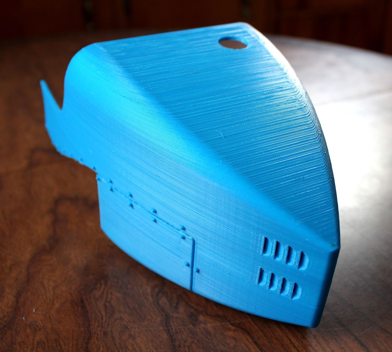
Just below the blue top cover plate is the sensor circuit board that make this assembly actually work.  Just a simple on/off switch that comes on when the filament runs out.  This assembly mounted perfectly to my 3D printer but had a flaw in the design and I put off correctly it until yesterday.  

The problem with this setup was that it was difficult to install new filament through this assembly and have it also be fed easily into the stepper motor drive assembly at the same time.  It seemed at times to have no issues and other times I would fuss with it for 10 minutes or more to get new filament loaded into the printer.  An issue that had become more and more frustrating while trying to 3D print parts.

What was going on was that the original mount made loading new filament into the machine simple because the sensor could be removed from the printer first. Then new filament was passed through it's opening and then on to the stepper motor drive assembly opening.  Once this was accomplished all that was needed to be done was remount the sensor assembly and printing could continue on before the reload was needed.  But this just put everything back the way it was where the filament sensor would eventually vibrate off of the printer once again over time. 


To finally eliminate the bad part of the first redesign I had to make the modification just a bit more user friendly.  In the image above you can see the first redesign on the left and the second redesign on the right.  On the left redesign the yellow column is mounted to the 3D printer along with the sensor switch, blue cover plate, three mounting screws and the larger bolts and nuts to hold the assembly to the 3D printer.  Again this looked good but made it difficult to reload new filament as it could not be removed from the machine while trying to put in new filament.

On the right you can see the new improved filament sensor assembly.  In this assembly you can see the redesigned yellow sensor mount, four neodymium magnets, a red sensor mounting housing, the sensor circuit board, the blue circuit board cover plate, three cover plate screws, and the large mounting bolts, nuts and spacers for the complete assembly. 

This new assembly now has a solid mount as before and the capability to remove the sensor from the assembly quickly and easily because of the small magnets between the upper and lower sections of the assembly. 


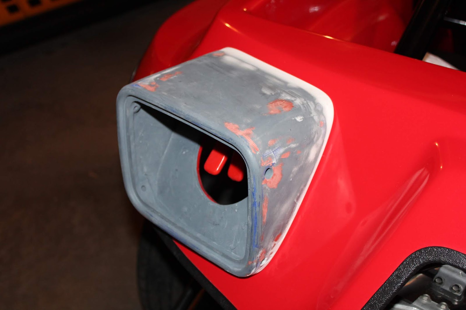
In the photo above you can see the new assembly mounted on to the 3D printer.  The white arrow is pointing to the filament out sensor, the orange arrow to the stepper motor that moves the filament into the printer, and the green arrow shows the upper mounting bolt that holds the top portion of the lower assembly firmly in place.   

The new magnetic mounts for the filament sensor are strong enough to hold the sensor in position while 3D printing but not so strong that it makes it difficult to pull the switch off of it's mount while reloading the machine with a new spool of filament.  

I think this will be the perfect solution to the problem that I was having with my first redesign.  As I said from the start sometimes you have to use the new design for a while to make sure it is what is needed to fix the original problem with a design. In my case I ended up finding an additional problem simply because I could nto remove the sensor while loading new filament into the printer.

 I will use the new setup for awhile to make sure I have everything ironed out the way I want. If not then I will try again but for right now this looks to be the best solution to the original issue as well as the found issue I was having with the filament sensor.  At least I hope so anyway.  Time will tell.  

Tuesday, June 18, 2019

New LED Dune Buggy Signal Lights Project Is Completed!


This week on the blog I put the finishing touches to the LED dune buggy signal lights project.  This is how it all turned out.


Here once again is how one of the housings for the new LED tail lights looked after having been sanded and primed for the first time.  As you can see it is "OK" at best as it is nowhere near ready for paint and it doesn't fit the profile of the body as properly as it should. 


To solve the fit up issue I covered the body with plastic and then remounted the LED housing to it's original position using small spring clamps.  I then puttied the mating surfaces of the housing and the body where they met up.  The putty is a mixture of fiber glass resin and micro-balloons. Micro-balloons are micro-spheric  hollow glass balls that make up a lightweight filler when mixed with the resin. I let the putty mixture cure overnight and then removed it from the dune buggy. 


Here you can see the difference from the first fit-up of the housing to the body of the dune buggy.  A perfect fit now that it has been sanded smooth to match the profile of the housing.  


The back of the housing for the LED tail lights had a large 4.5" diameter hole in the design.  This was exactly the size of hole that was cut into the body of the dune buggy for the old tail lights.  With the housing having the same  size opening it made it simpler to align the lights to the body of the dune buggy and have both lights positioned correctly when mounted.  It also made mounting the  new housings to the body easier as well by allowing me to mark and drill the new mounting holes for the housing.  

The one drawback to having such a large hole was what to do with such a large opening after the lights had been installed.  A perfect doorway for any little critter to call home so another part needed to be designed and installed. 

The yellow part in the image above was the answer.  This little cover was mounted to the inside of the housing to seal the large opening yet allow the wiring to be inserted into the housing for the LED lights with a much smaller hole. 


These two images best display how the new housing cover was mounted into the assembly.  This was easily done with the same putty mixture that I used to get the fit up corrected for the housing and body.   I bonded the cover to the inside of the housing and then let the epoxy resin putty again cure overnight and the little cover was then secured permanently in place.


After the housing had been properly sanded and painted a nice glossy black, I was able to finally get at the last step of the project and mount and wire up the new tail lights.  


The new LED lights are a vast improvement from the old tail lights that were in the car.  This also really improved the look of the tail end with the 1964 Mustang tail lights.  I really like the chrome trim and the red accent that I used that is around the tail lights.  


With the housings for the tail lights being painted glossy black it matches nicely with the rest of the black that is already in the car.  It took me some time to get the wiring all nicely tucked away under the body of the car so that was the major part of the work to the installation of the lights.  


I have to give a big shout out and thanks to my brother Carl who painted the LED tail light housings for me.  He did a wonderful job in one day's time where it would have taken me a week to get the results that he is very skilled at.  Thanks brother!

Now I can take the rest of summer and get some miles on the little dune buggy and show it off at some of the local car shows in the surrounding area.